
Excavator or backhoe calibration
To determine the position of the various moving segments on an excavator (boom, stick, bucket etc...), angle or gravity sensors are mounted on these segments to tell the software their position. Since it is not always possible to mount the sensors absolutely in line with the segment, or they can be a little off, you have to calibrate the sensors. In Hydromagic Dredging, calibration can be done by adding an offset to all measurements. You could use a leveler and correct all values by hand, but since the segments of the excavator form a triangle, we can use math to fix this problem.
Preparation
Before starting the calibration process:
- Make sure all sensors are powered on and connected to the system;
- Check whether the correct plugin for your dredging system has been loaded;
- Check whether sensor values are coming in;
- Make sure that the segment lengths are entered correctly;
- Make sure the dog bone dimensions have been entered when the sensor is not placed on the bucket itself.
To start the calibration tool, select the "Preferences..." option from the "Options" menu. Next click the "Dredging" tab and double-click the excavator in the dredging equipment list. When the equipment is configured as excavator or backhoe dredger, the "Calibrate Excavator..." button should be visible.
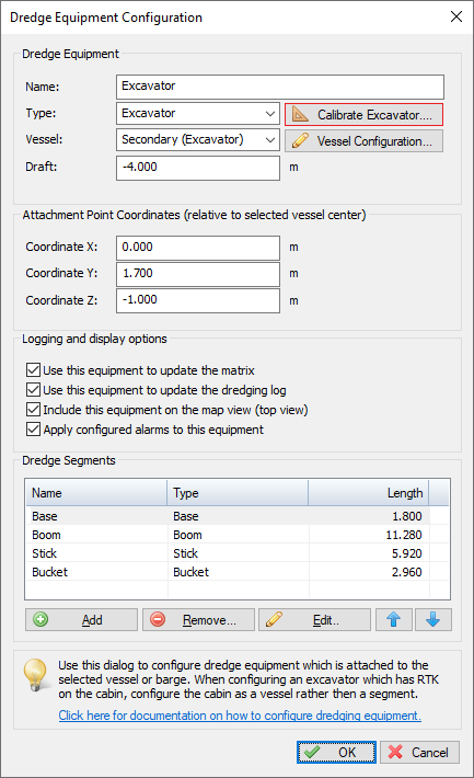
Click the "Calibrate Excavator..." button to open the calibration tool.
Positioning the excavator
Before starting the calibration, we have to position the excavator to form a triangle with the bucket vertical and the tooth at the same level as the barge deck or ground. The image below should make things more clear.
When the excavator is in the correct position, you have to do two measurements:
X1 Measurement
Measure the distance between the joint on the base to the joint on the bucket. Please note that the length has to be measured between the center of the joints. If needed convert the length to meters and write it down.
H1 Measurement
Measure the distance between the joint on the base and the ground or deck of the vessel. Please note that you have to measure from the center of the joint. If needed convert the length to meters and write it down.
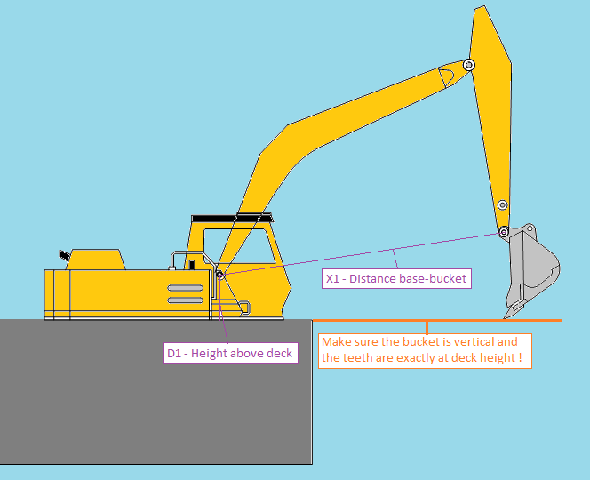
Measure the D1 and X1 distances in order to calibrate your excavator or backhoe.
Starting the calibration tool
When the measurements have been taken and the excavator is still in the correct position and the sensors are sending data, we can start the calibration tool. Please go back to the excavator settings and locate and click the 'Calibrate Excavator...' button.
The parameters needed for the calibration are the segment lengths as well as the X1 and H1 values we measured. The lengths are already filled in, you only have to supply the X1 and H1 value.
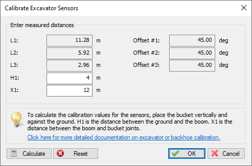
Enter the 'X1' and 'H1' measurements and click 'Calibrate' to calibrate the angle sensors.
Before doing so, reset any previous calibrations by clicking the 'Reset' button. After you have filled in the correct values, click the 'Calculate' button. The software will display the suggested calibration settings. Now click 'OK' to accept them
After calibration, the dredging view should display the same positions as the 'real' excavator.
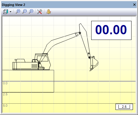
The digging view should look like this after calibration.