
Dredging Equipment
In Hydromagic Dredging, you can configure one or more pieces of dredging equipment depending on the license you have bought. Three different license models are available:
Single Head License
With the single head license you can monitor one dredge head only. This option will probably be sufficient for most cutter and trailing suction hopper dredgers. This license limits the number of dredge heads that will be recorded to just one. You are allowed to configure multiple pieces of equipment, but only one can be used at a time.
Dual Head License
To monitor a trailing suction hopper dredger with two suction tubes, you need the dual head license to be able to monitor two dredge head positions at a time.
Excavator or Backhoe License
To monitor the position of an excavator or backhoe dredger, you need this license. It supports monitoring of the excavator position, rotation and you can display the barge and excavator independently.
Dredging Equipment Configuration
Dredging equipment can be configured by selecting a vessel, attachment position and by adding the segments that make up the dredging equipment, for instance, when configuring a backhoe dredger, you select the barge, position on the deck and the cabin, boom, stick and bucket segments. Because of this modular approach, you can configure almost every type of equipment. For instance, when your excavator contains a second boom, you just load the standard excavator configuration and adapt it by just adding a new boom segment.
To start configuring dredging equipment, select the "Preferences..." option from the "Tools" menu and select the "Dredging" tab. In the "Dredger Configurations" list, the already configured items will be displayed. You can remove the existing item(s) by selecting them one by one and clicking the "Remove..." button. Now you can add a new configuration item by clicking the "New..." button.
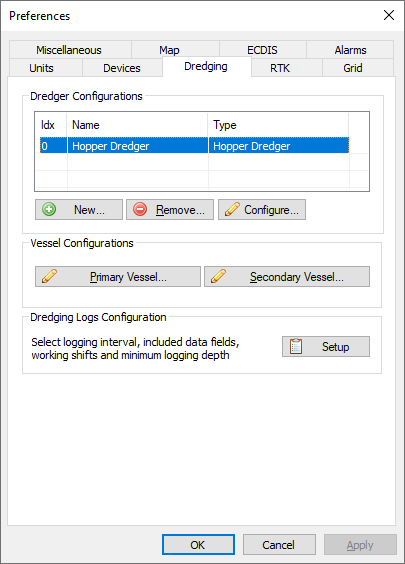
Click the "New..." button to add a new dredging equipment configuration.
Adding new equipment
After clicking the "New..." button the "Dredge Equipment Configuration" dialog will be shown. In this manual, we will call each suction tube, excavator or other tool "Dredge Equipment". First add a name for the equipment. This is how we can select it in the data or digging views. This is also the name written to the log file when the "Dredge Name" field is included. Since it could be written to a file, no special characters other than alphanumeric characters and spaces are allowed. Good examples are: "Hopper Dredger (STBD)", "Hopper Dredger (PORT)", "Cutter" or "Excavator".
Use the "Type:" drop down box to select the type of equipment. Examples include: "Excavator", "Backhoe", "Cutter" and "Hopper". It is important to set this option correctly, otherwise you won't be able to configure the dredge segments correctly.
Dredging equipment has to be associated with a 'Vessel' to which it has been attached. You can select a vessel from the drop-down list. For all configurations other than excavators, you should choose the first option (Primary). You can read more on vessels in the "Configuring Vessels" document.
After selecting the vessel, click "Vessel Configuration..." to choose the shape file used for display.
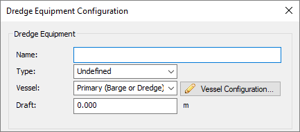
The first section of the dialog contains some important global settings.
Attachment Point Coordinates
The dredging equipment is always attached to the vessel. In order to calculate the correct easting and northing coordinates for the dredge head, you have to enter the coordinates of the attachment point relative to the vessel's center point. After importing a drawing of your vessel into the "Vessel Designer", you can place a pivot point at the attachment position to read out the XYZ coordinates of this point as shown in the image below.
Regarding the vessels center point, it doesn't really matter how you center your vessel around the (0, 0, 0) coordinate in the vessel designer, as long as all sensors are relative to this point (attachment point, draft sensor and GNSS antenna).
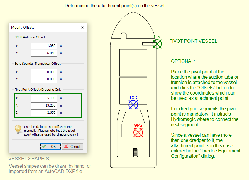
The attachment points can be determined by analyzing a drawing of the vessel in the "Vessel Designer".
Logging and display options
In the logging and display options section, you can select whether or not to use the dredge head position to update the matrix or log file. You can also disable alarms for this dredge head. This can be useful when you have two suction tubes on a hopper dredger and a sensor on one of the tubes is malfunctioning. In this case, you can still log data from one dredge head.
Various (logging) options for the selected dredge equipment.
Dredge Segments
In the dredge segments section, you can add all the segments that make up the dredge equipment. The following segments can be defined:
- Cutter Dredger: Ladder and cutter head;
- Trailing Suction Dredger: Trunnion, ladder and dredge head;
- Excavator: Base, cabin, boom, stick, quick attachment, dog-bones and bucket;
Use the "Add..." button to start adding a new segment. With the "Edit..." button you can access calibration options or change the length or length of a segment. It is important to add the segments in the correct order. The segment which is attached to the vessel comes first, and the dredge head or excavator bucket last. You can change the order of the segments by selecting the item you want to move, and clicking the up and down arrows to move the item up or down the list.
For more information on the types of segments, and how to configure them, please refer to the "Configuring Dredger Segments" manual page.
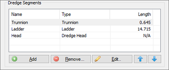
In the "Dredge Segments" section you can define the segments of your dredge equipment.