
Multi beam echo sounder (MBES) capabilities are only supported in Hydromagic version 2025 and newer.
An additional license is required to record and process MBES data.
Perform Multibeam Patch Test
The Perform Multibeam Patch Test module calculates and applies the exact mechanical mounting offsets (boresight calibration) between your vessel's Motion Reference Unit (MRU) / GNSS antenna and the Multibeam Echosounder (MBES) transducer.
Because the transducer is rarely perfectly aligned with the vessel's axes, microscopic angular errors will cause massive depth and positioning artifacts. This utility allows you to visually align overlapping survey lines to calculate and apply corrections for Latency, Roll, Pitch, and Yaw.
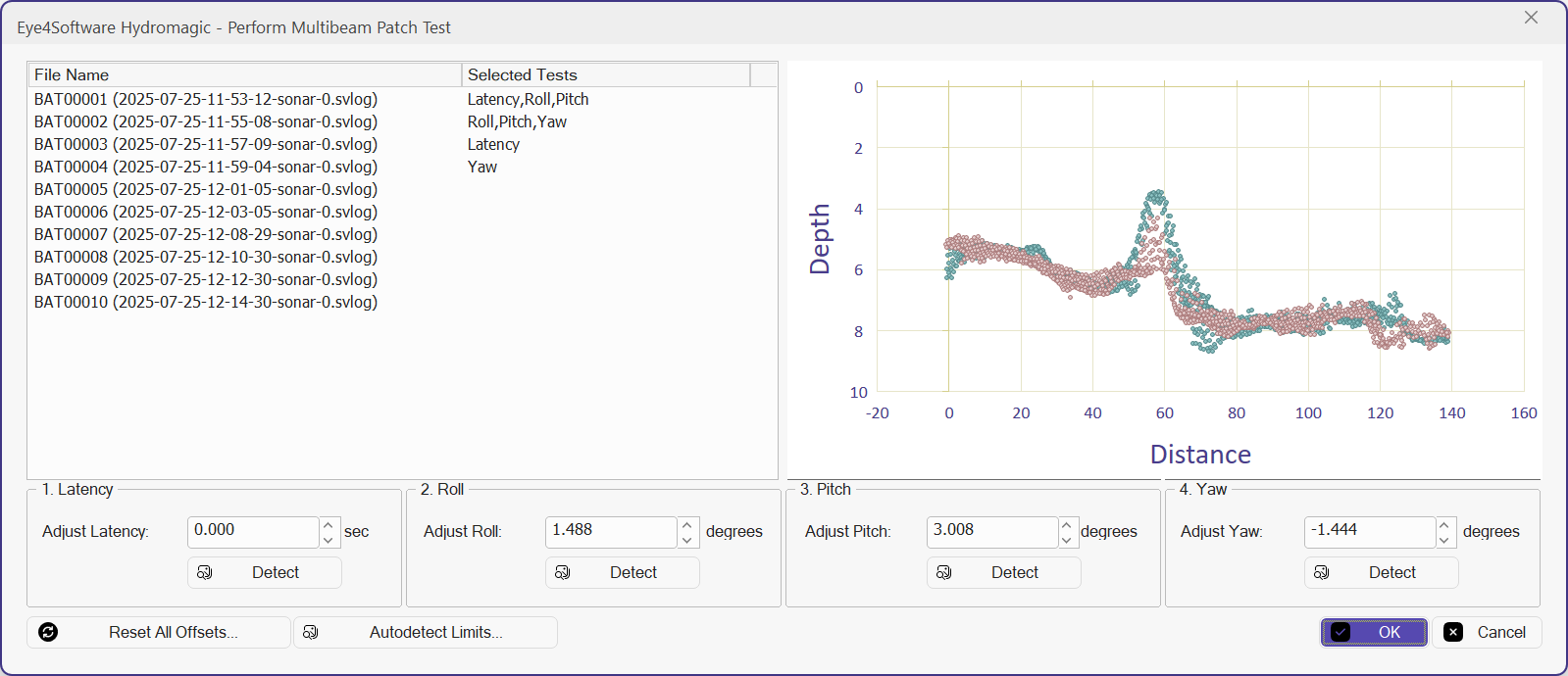
Before processing multi beam data, run a patch test to calibrate your sensors.
Pre-Calibration Checklist
Before determining your angular offsets, the physical coordinate frame and water column physics must be strictly defined. Failure to set these correctly will invalidate your patch test.
-
Lever Arm Offsets (Target minus Origin)
- Your GNSS Antenna is the physical origin (0,0,0). You must define the exact physical distance to the Transducer.
- X (Across-track): Positive (+) to Starboard, Negative (-) to Port.
- Y (Along-track): Positive (+) Forward, Negative (-) Aft.
-
Vertical Offsets (Draft & Height)
The ray-tracing engine automatically isolates vertical offsets. The total Z-distance (Draft + Antenna Height) is used for RTK elevation, while the static Draft is used exclusively to calculate dynamic induced heave.
-
Sound Velocity Profile (SVP)
A valid sound velocity profile must be applied to correct for ray-bending through the water column before calculating angular offsets.
Interface Overview
The Patch Test window is divided into three main sections:
File Selection
Displays your loaded raw survey files (e.g., BAT00001) and the specific calibration tests assigned to them (e.g., Latency, Roll, Pitch, Yaw).
Profile Graph
A 2D slice of the seafloor plotting Distance vs. Depth. It overlays the point clouds from two different survey passes (distinguished by color, such as teal and pink). Your goal is to adjust the offsets until these two point clouds perfectly merge.
Adjustment Controls
Four numbered panels corresponding to the four calibration steps. Each contains a numeric input box and an automated Detect button.
Step-by-Step Calibration Procedure
1. Latency (Timing Delay)
- What it fixes: A timing mismatch between the GNSS/MRU output and the sonar ping. This causes features to appear shifted along the vessel's track.
- How to test: Select two files driven over a prominent feature (like a slope or wreck) in the same direction, but at significantly different speeds.
- Adjustment: Use the Adjust Latency (sec) arrows until the features perfectly overlap on the Profile Graph.
2. Roll
- What it fixes: A constant tilt of the transducer port or starboard. Uncorrected roll results in a flat seabed appearing tilted, or overlapping outer beams looking like "steps."
- How to test: Select two files driven over a flat seabed in opposite directions at the same speed.
- Adjustment: Use the Adjust Roll (degrees) arrows to flatten the step between the two colored point clouds. The engine applies this offset directly to the dynamic motion data to level the outer beams.
3. Pitch
- What it fixes: A constant tilt of the transducer forward or backward. Uncorrected pitch causes a target to appear in different along-track positions depending on the vessel's direction of travel.
- How to test: Select two files driven over a prominent feature in opposite directions at the same speed.
- Adjustment: Use the Adjust Pitch (degrees) arrows to slide the point clouds horizontally until the target peaks align perfectly.
4. Yaw (Heading)
- What it fixes: A rotation of the transducer relative to the vessel's centerline. Uncorrected yaw causes the outer beams of overlapping swaths to sweep forward or backward, skewing features on the seafloor.
- How to test: Select two parallel, overlapping files driven in the same direction over a prominent feature or slope.
- Adjustment: Use the Adjust Yaw (degrees) arrows until the slope or feature aligns. The software adds this value directly to the interpolated GNSS heading before transforming the beam coordinates.
Automation and Tools
- Detect Button: Located under each adjustment field. Click this to command the software to mathematically analyze the two point clouds and suggest the best-fit offset value automatically.
- Autodetect Limits...: Configures the search boundaries for the mathematical
Detectalgorithm, preventing the software from locking onto false positives (e.g., restricting the roll search to +/- 5 degrees). - Reset All Offsets...: Clears all fields back to 0.000, allowing you to start the calibration over from the raw sensor data.
Once all four values are dialed in and the point clouds perfectly overlap, click OK to commit the variables to the survey configuration and re-process the multibeam swaths.