
Hydromagic 3D Terrain Viewer
The Hydromagic 3D Terrain Viewer is a standalone utility which can be used to view generated matrices like a 3D surface, point cloud, or wireframe. The view generated by the terrain viewer gives an accurate image of the bottom of the surveyed area, and you will see which areas need more filtering in the blink of an eye. You can use the terrain viewer to view matrices generated in both Hydromagic Survey and Hydromagic Dredging.
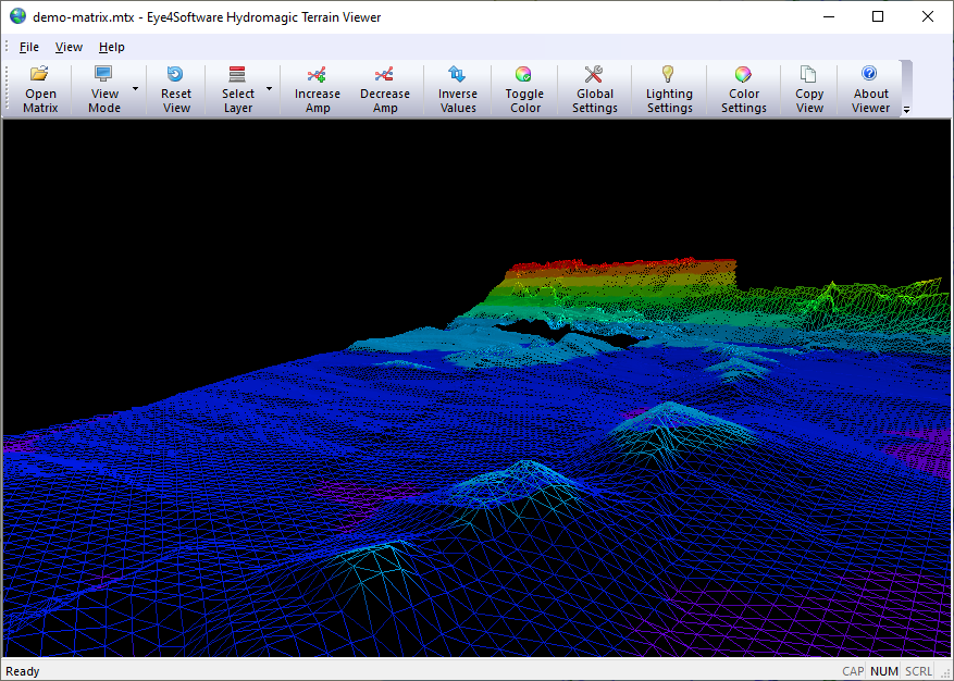
The main screen of the 3D Terrain Viewer shows a detailed image of the bottom.
Starting the Hydromagic Terrain Viewer
The tool is installed in the "Program" folder under the installation folder of the software. It can be started using Windows Explorer, or by locating the software under the Windows Start Menu. Alternatively, you can start the "Terrain Viewer", by right clicking a generated or loaded matrix in the "Project Explorer" and selecting the "Open in Terrain Viewer..." option."
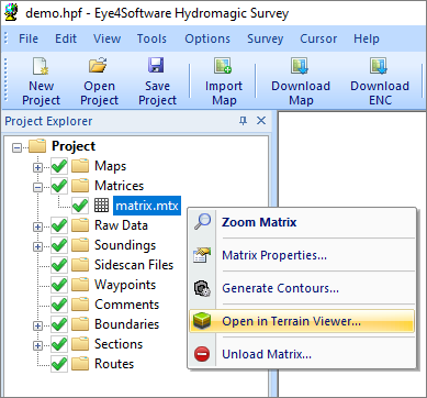
Start the "Terrain Viewer" by right clicking a matrix.
Loading a matrix file
When opening the terrain viewer from the "Project Explorer", the selected matrix file is automatically loaded. When starting the software directly from the Windows Start Menu or Hydromagic program folder, no matrix will be loaded and you can open a matrix file (*.mtx) by clicking the "Open Matrix" button in the tool bar, or selecting the "Open..." option from the "File" menu.
View Modes
A matrix file can be viewed in 3D in different view modes:
- Fill - All matrix cells are divided in triangles and filled with a solid color;
- Wireframe - All matrix cells are divided in triangles and the outlines of the triangles are drawn;
- Pointcloud - All matrix cells are drawn as pixels with the associated color and offset;
When drawing the matrix as a wireframe or pointcloud, the line width and pixel size can be adjusted by clicking the "Global Settings" button in the tool bar. To change the current view mode, click the "View Mode" button to select the desired mode from the drop down menu, as shown in the screen shot below:
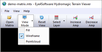
Selecting a different view from the "View Mode" menu.
Rotating and zooming
The terrain can be viewed from different angles and distances. Just imagine a camera that is rotated around the object to view it from a different angle. By zooming in and out, basically this virtual camera moves closer towards or further away from the object. You can control the rotation around the object by moving the mouse while holding the right mouse button. To zoom in and out, use the scroll wheel on your mouse. If you want to return the "Camera Position" to the start position, click the "Reset View" button in the tool bar.
Layers
Depending on which Hydromagic software is used to generate the matrix, it can contain only one or multiple layers. In Hydromagic Survey only one layer will be created, while Hydromagic Dredging will create three layers by default (pre-dredging, dredging and post-dredging). To select which layer of the matrix is shown in the terrain viewer, click the "Select Layer" button to select the active layer from the drop down menu as shown in the screen shot below:
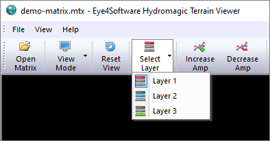
Switch between different layers using the "Select Layer" menu.
Amplification (Z-Values)
By default, the matrix 3D model is scaled equally in all directions. In some cases, for instance, when you want to view a large area, it might be useful to adjust the Z scaling to exaggerate the depth or elevation levels to be more clearly visible. You can do this by using the "Increase Amp" and "Decrease Amp" buttons in the tool bar. Alternatively, you can set the amplification level manually by clicking the "Global Settings" button and using the "Factor" setting in the "Amplification" section.
Inverse Values
When you load a matrix with elevation values instead of depth values, the terrain might be mirrored in Z-Direction. In these cases, just click the "Inverse Values" button to mirror the Z-Values of the model.
Color Settings
In the "Terrain Viewer", 3D terrains can be viewed in multiple colors or a single color. To switch between single and multiple color mode, click the "Toggle Color" button. When in color mode, different depth or elevation levels will have different colors, just as you used to when displaying matrices in the survey or dredging program. To configure color ranges, click the "Color Settings" button. You can create multiple color ranges which can be set automatically. You can also import color schemas created in either the survey or dredging program.
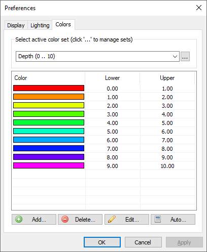
From the "Colors" tab, you can create, import or configure color sets.
Global Settings
Click the "Global Settings" button to change some global and miscellaneous settings, like background color, amplification factor, view mode and more. Some of the settings can also be accessed directly by the tool bar, including the "View Mode", "Miscellaneous" and "Amplification" settings. In this dialog, you can also change the point size and line width for the 'Wireframe' and 'Pointcloud' view modes.
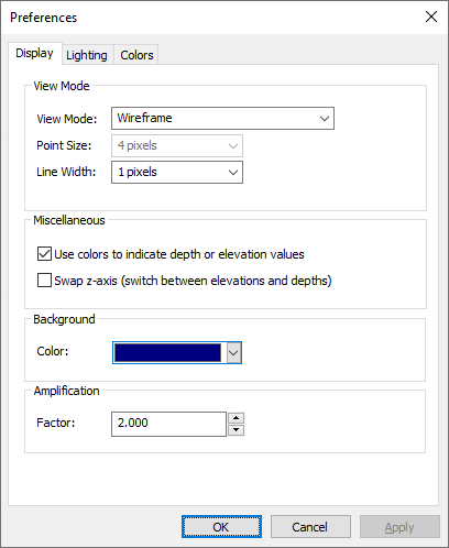
From the Display tab, you can alter some
global and miscellaneous settings.
Lighting Settings
In the "Lighting Settings" can be used to define an optional light source. By default the objects drawn will "emit light" by themselves. When enabling lighting, you can create shadow effects by setting the direction of the light. To use an alternate light source, click the "Lighting Settings" button and check the "Enable lighting" check box. With the "Direction" and "Pitch" sliders you can move the light source around the 3D model. When moving a slider, the new position of the light is applied to the model directly, making changes visible instantly.
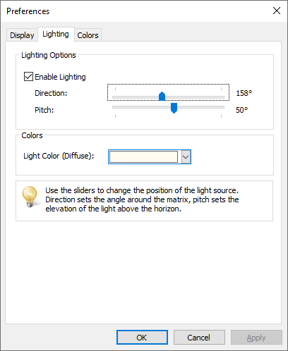
Create shadow effects by setting an alternate light source.