
Multi beam echo sounder (MBES) capabilities are only supported in Hydromagic version 2025 and newer.
An additional license is required to record and process MBES data.
Using the Hydromagic Multi Beam Editor
Since version 2027 of Hydromagic Survey, the software is shipped with a 3D multi beam editing tool which can be used for patch testing, data filtering, data editing and more. After processing the swath data, the data can be converted to a matrix or DTM which can be exported in various data formats.
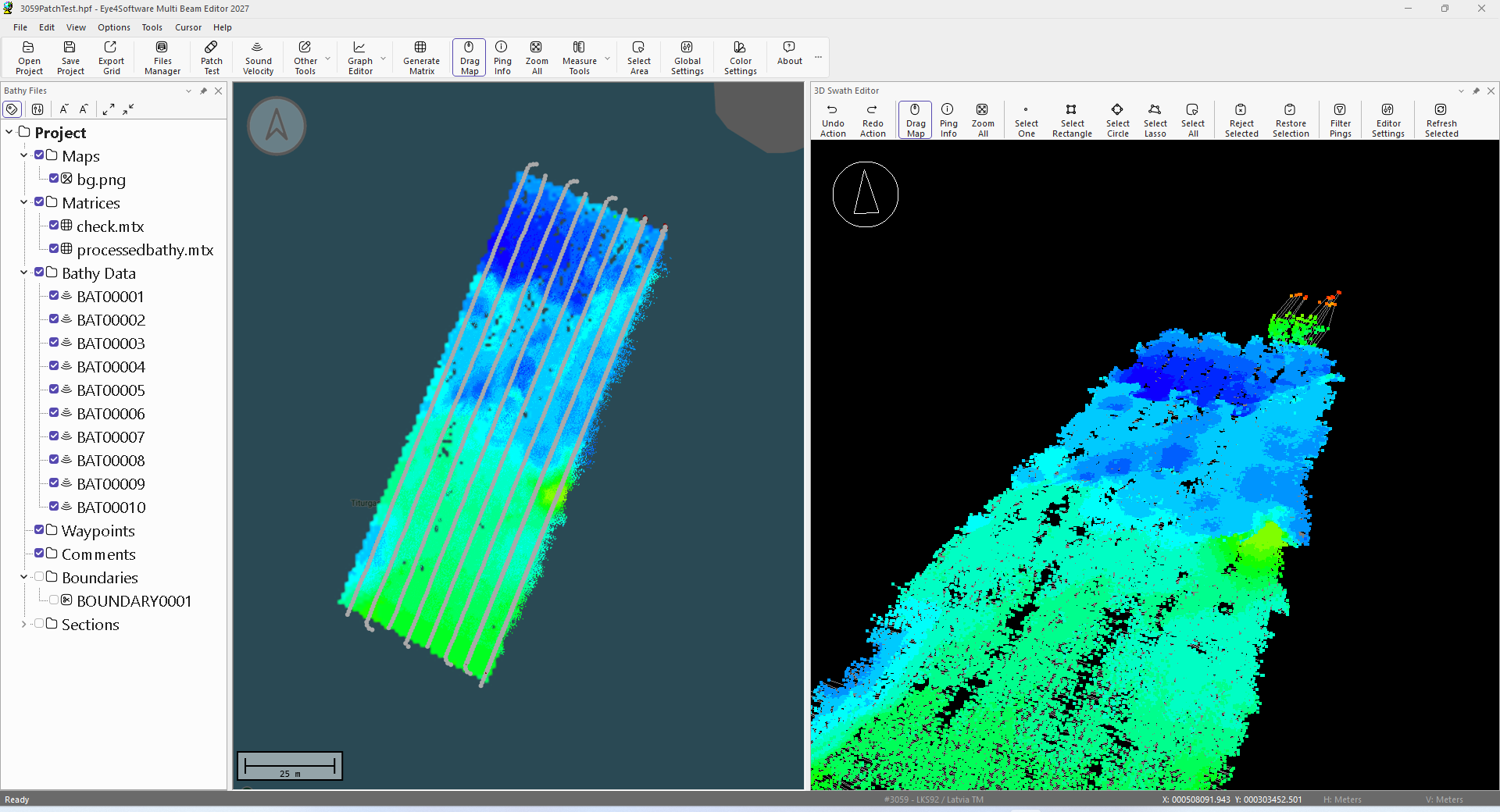
Hydromagic Multi Beam Editor showing MBES point cloud data.
To process raw multi beam files, please follow the following workflow to get the best results:
- Make sure all offsets have been set (lever arm offset), like GNSS antenna position, transducer offset and motion sensor position using the Vessel Designer;
- Create a sound velocity profile for the sounding. This can be done in the built-in sound velocity profile editor tool;
- Make sure motion sensor and heave settings are correct;
- When you recorded data for patch testing, execute the patch test before starting to edit your data;
- Generate a matrix for the data which can be used to navigate through your point cloud data;
- After successfully performing the patch test, you can use the built-in filters and editor to clean the data (spikes);
- When data has been cleaned, you can regenerate the matrix and export it into various formats.
1. Set lever arm offsets
These offsets are important to calculate the distance between the GNSS antenna and the beam returns. Without this information the software assumes that the beams originate from the same position as the GNSS receiver. Because heading is also required to calculate these offsets, please make sure the software is recording your actual heading during your survey.
The horizontal and vertical offsets for the GNSS antenna, multi beam transducer and MRU or motion sensor can be defined using the "Vessel Designer utility which is shipped with all versions of the software. When not set correctly, vessel offsets can always be corrected after your survey has been recorded.
You set the vessel file containing the offsets in the software's preferences window which can be accessed by selecting the "Preferences..." option from the "Tools" menu, or by simply clicking the "Global Settings" button in the main tool bar. When the preferences screen opens, click the "Calibration" tab to access the vessel design file.
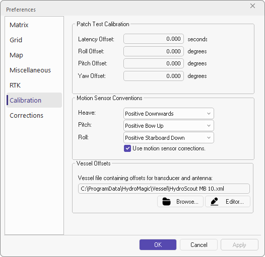
Select the correct vessel design to apply offsets.
2. Create a sound velocity profile
Because acoustic beams are refracted as they travel through layers of water with different sound velocities, a sound velocity profile is used to calculate the beam path and determine the sounding position more accurately. The complication is that sound speed normally changes with depth. To get the best accuracy it is recommended to use a sound velocity probe.
When surveying in shallow water, or when a sound velocity probe cannot be used, you can enter an appropriate measured or estimated surface sound velocity. The software can process the data without a full sound velocity profile, but accuracy may decrease as water depth and variations in sound velocity increase.
The "Sound velocity file editor" in the Hydromagic Multi Beam Editor is the same tool as used in the Hydromagic Survey application.
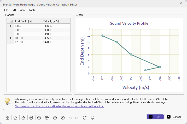
Use the built-in sound velocity editor to generate or import a SVP profile.
3. Check the motion sensor configuration
Before executing the patch test, it is very important to check the sign conventions used by your motion sensor. The default settings will be correct for most motion sensors, but it is important to verify them because incorrect sign conventions can result in substantial errors in the data.
You can find the motion sensors in the software's preferences which can be accessed by selecting the "Preferences..." option from the "Tools" menu, or by simply clicking the "Global Settings" button in the main tool bar. When the preferences screen opens, click the "Calibration" tab to access the motion sensor settings.
Always check the motion sensor conventions before performing the patch test.
4. Perform a patch test
To get the most accurate results, a patch test is needed because a multi beam system combines measurements from several independent sensors, such as the GNSS receiver, multi beam transducer and motion sensor, and their physical mounting can never be assumed to be perfectly known.
The patch test is used to detect these errors and calculate the offsets needed to adjust for them. You normally perform the patch test after collecting your data. While collecting data, you have to survey certain lines in a specific way so they can be used for the patch test.
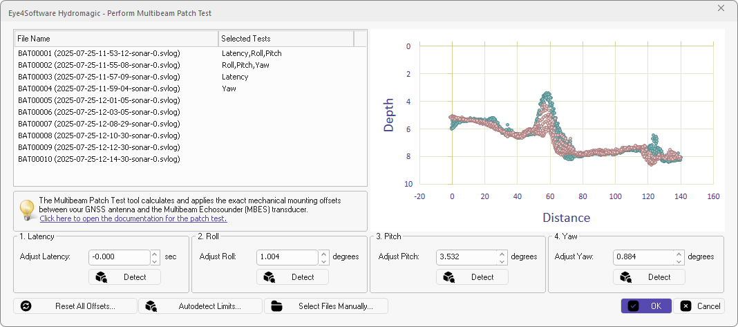
Use the Patch Test tool to calculate the required MBES calibration corrections.
5. Generate a matrix with the point cloud data
This step is optional, but it is recommended to generate a matrix to guide you through the data cleaning and filtering. With a matrix in the chart view, you can more easily locate the areas which need attention, or zoom in to data in the 3D editor.
To generate the matrix, just click the "Generate Matrix" button in the main toolbar. Next you can select the bathy files you want to include. Normally you only select the survey data itself and leave out lines recorded for the patch test. Make sure to select a boundary to clip the data to a certain area. The boundary can be generated by opening the same project in Hydromagic Survey.
Since we want to remove spikes from the data, do not use any of the filter options when generating a matrix yet. This can be used to remove some minor noise before exporting the data in the last step.
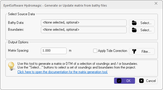
Generate a matrix with the point cloud data.
6. Filter and edit the point cloud data
You are now ready to manually edit or filter the generated point cloud data. The 3D point cloud data is displayed in the 3D Swath Editor on the right side of the screen. This screen has its own toolbar that enables you to select one point or a selection of points by using a rectangle, circle or freehand form. When you reject points in the selection, they are only marked as rejected and never deleted. To remove your selection, simply click the right mouse button. The restore button can be used to bring back a selection of points that have been rejected.
To automatically filter the data using a median filter or depth range, click the "Filter Pings" button.

Click the Filter Pings button to filter the data.
7. Export the data as matrix or DEM file
During the editing of the data you can regenerate the matrix to see if the data is ready to be exported. When you are happy with the results, you can Export matrix data in various third-party data formats.
In case you want to use the data in Hydromagic Survey for further processing (for instance volume calculations, cross sections, or contours), you have to export the matrix data in "Hydromatic Matrix File (*.mtx)" format. This way you can simply import it in Hydromagic Survey for further processing.
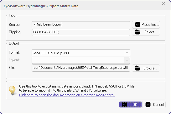
When finished editing data export it as DEM file.