
Motion sensors
Since Hydromagic version 6.0, the software has built-in support for motion sensors or MRUs. Motion sensors can be used to correct your soundings for heave, pitch, and roll motions of the vessel.
Hydromagic uses the motion sensor measurements to calculate, together with the beam width settings, the corrected bottom depth and the transducer and GPS antenna position displacements. To calculate the displacements, a valid heading (true or magnetic) is required.
In Hydromagic, motion sensors are configured using hardware plugins supplied with the software. Supported devices include Teledyne TSS, SBG Systems, IMU and compatible hardware. To use a motion sensor, you first have to load the "plugin" so it can interface with Hydromagic Survey or Hydromagic Dredging. Please note that some echo sounders (including CEE HydroSystems and EchoLogger) have a built-in MRU. In such cases no additional plugin is required.
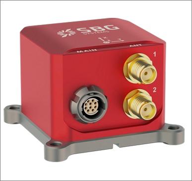
SBG is one of the MRU brands supported by Hydromagic
Device (sensor) location offsets
Whether you are using a motion sensor or not, always make sure that the locations of the device sensors, like the GNSS antenna, echo sounder transducer, and motion sensor, are specified using the ""Vessel Designer"" utility. When motion sensor readings are used, these offset locations are corrected using the pitch and roll values reported by the sensor. When the motion sensor is used for heave, make sure to specify the location of the motion sensor (MRU) as well (orange in the "Vessel Designer").
To start the "Vessel Designer" utility, open the preferences dialog by selecting "Preferences..." from the "Options" menu. In the preferences dialog, select the "Map" tab, and click the "Editor..." button to start the utility.
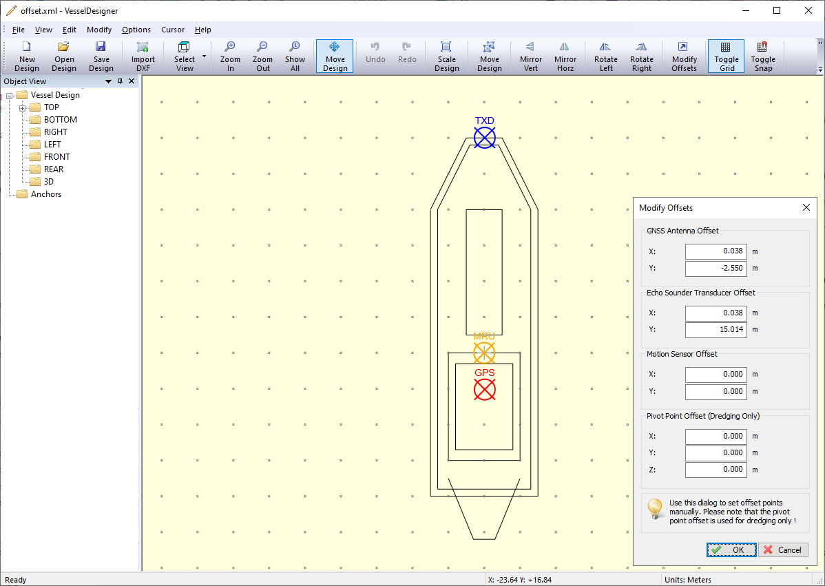
Make sure the locations of the devices or sensors are set using the "Vessel Designer" utility.
Motion sensor calibration
A motion sensor can be calibrated in the "Motion Calibration" section of the preferences window. To open this tab, select "Preferences..." from the options menu, and select the "Calibration" tab. The below window should appear:
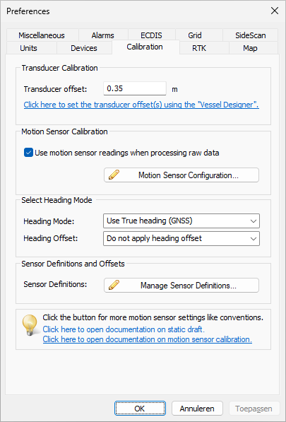
Calibrate the motion sensor before each survey.
To include the motion sensor data during post-processing calculations, make sure the "Use motion sensor readings" option has been checked. In cases where the sensor is malfunctioning (reporting invalid values), you can simply disable it by unchecking this option. This is especially useful in cases where you cannot just unload the device's plugin, for instance when the motion sensor is integrated in the echo sounder or transducer.
Before performing the survey, make sure the motion sensor is calibrated. If needed, launch the boat in calm water, make sure each crew member is at his station and enter the (inverted) pitch and roll readings as shown in the "Data View". For instance, when the pitch and roll are 0.8 and -1.2 degrees, respectively, enter -0.8 as the pitch offset and 1.2 as the roll offset in the calibration window. To enable calibration, make sure the "Use motion sensor offsets" option has been checked. After applying these settings the new pitch and roll readings in the data view should be zero or almost equal to zero.
Motion Sensor Configuration
When setting up a motion sensor for the first time, some additional parameters must be set, like rotation axes directions and the beam width of the echo sounder's transducer. The beam width of the echo sounder is needed to calculate the beam displacements. Use this "Use beam steering" option when you encounter pitch and roll higher than twice the beam width of your echo sounder.
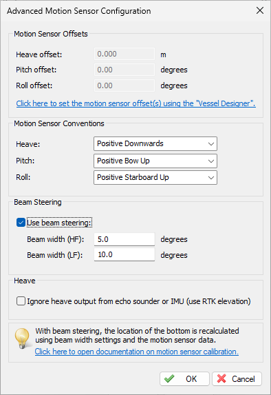
The Advanced Motion Sensor Configuration dialog.
Motion Sensor Conventions
Different brands of motions sensors use a different convention for the direction of the X, Y and Z axes. This is why the settings in the "Motion Sensor Conventions" section are very important. An incorrect setting can result in less accurate data. Please refer to the user manual of your motion sensor on how to interpret the motion values. Here are the settings for some commonly used motion sensors:
Applanix
| Direction | Convention |
|---|---|
| Pitch: | Positive Bow Up |
| Roll: | Positive Starboard Down |
NMEA0183 $PRDID
| Direction | Convention |
|---|---|
| Pitch: | Positive Bow Up |
| Roll: | Positive Starboard Down |
SBG
| Direction | Convention |
|---|---|
| Heave: | Positive Downwards |
| Pitch: | Positive Bow Down |
| Roll: | Positive Starboard Down |
TSS1/TSS2
| Direction | Convention |
|---|---|
| Heave: | Positive Upwards |
| Pitch: | Positive Bow Up |
| Roll: | Positive Starboard Down |
In the event that a sounding is done with incorrect motion sensor settings, it is always possible to correct this during post-processing of the data in the "Sounding Wizard" (via the "Offsets Tool"). In the offsets tool, just click the "Swap Sign" option for the direction you want to correct. If your motion sensor does not support heave, just ignore this setting.
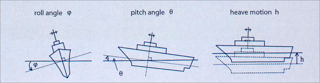
Possible motions which are reported by your motion sensor.
Beam Steering
The beam steering option uses the sounder's beam width information, together with the pitch and roll data and the sensor position offsets, to calculate the new position of the beam on the bottom. We recommend to use this option when there is a lot of motion and you are using an echo sounder transducer with a low beam width. The beam angles for your sounder can be found in its documentation. Please note that this beam angle(s) depend on the transducer used with the sounder, so you might want to double check with the manufacturer of the transducer as well. Common ranges for high frequency transducers are 3-8 degrees, while they are usually wider at lower frequencies, in the range from 8 till 24 degrees.
Heave
Heave is used to correct the vertical motion of the vessel, caused by for instance, waves. It is important to disable heave compensation by a motion sensor when heave is corrected within the hydrographic echo sounder. To do this, select the "Echo sounder outputs heave corrected depths" checkbox. The heave offset box will be disabled as well.
Testing the motion sensor
When the plugin for the motion sensor has been loaded, the current pitch, roll and heave values (when applicable) should be displayed in green in the "Data View" window. Please note that the calibrated values will be displayed here, so values of 0.0 could be displayed.
The second test is to check whether the data is recorded correctly to a raw data file. Motion data will always be recorded, no matter whether the motion sensor has been enabled in the "Calibration" tab of the preferences dialog. When this checkbox has been disabled, it means that the motion data will be ignored while post processing the data. When a project has been created or loaded, click the record button to record some data.
After stopping the recording, right-click the file you just recorded in the "Projects Explorer" and select the "Analyze Data" option. Click the "Next Data" button till the motion data is displayed (like in the screenshot below). Depending on the motion sensor you own, two or three columns should be filled with data. Please note that this table contains the values as reported by the sensor, without calibration offsets and axis conventions applied.
Since offsets and axes directions have not yet been applied to the raw data, you will always be able to reprocess the data with a different motion sensor configuration. Just go to the "Advanced Motion Sensor Configuration" screen by clicking the "Motion Sensor Configuration..." button in the "Calibration" tab. After making changes to the configuration, just launch the "Sounding Wizard" again.
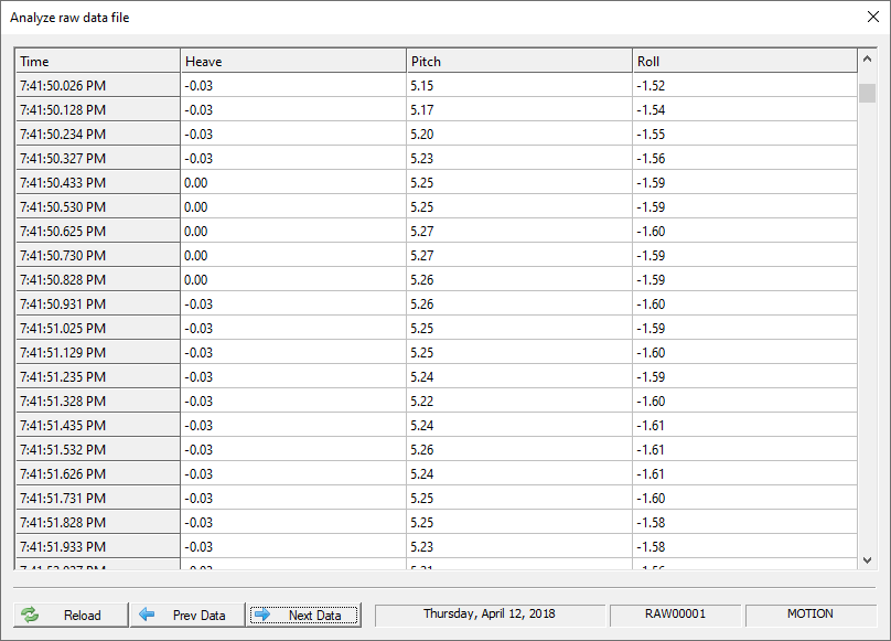
The recorded motion data can be viewed in the Raw Data Analyzer tool..
Apply the motion sensor data
To apply the motion data to your soundings during the post-processing of the raw data, make sure the motion sensor configuration has been enabled as discussed in the "Motion Sensor Calibration" paragraph above. During this process you will also be able to filter the pitch and roll data, apply additional offsets or to reverse the directions of the axes.
After generating the soundings, you can check the soundings by right clicking a ping in the map display and selecting the "Edit Sounding Data" option. The interpolated heave, pitch and roll values used to calculate the new depth and sounding position are displayed. The heave is expressed in vertical units while the pitch and roll values are always in degrees.
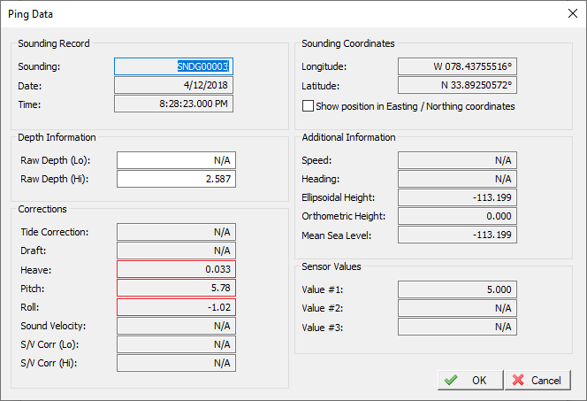
The heave, pitch and roll values applied to a single ping can be viewed.