
Cross Sections in Hydromagic
In Hydromagic, cross sections are 2D or 3D polylines that can be used for multiple purposes:
- As guidance lines when steering your boat during the survey (with or without the help of the built-in Helmsman display);
- To generate and export cross sections of your channel after surveying;
- When calculating volumes using cross sections;
- To create routes for your automatic pilot module using the built in route planner;
Cross sections are also called "planned lines" or "survey lines" in some software packages. In Hydromagic, cross sections are stored in the project file and can be transferred to another project by exporting them as ASCII data. Cross sections can be placed manually, generated by the software or imported from a CAD program that supports the DXF file format (for instance AutoCAD).
This YouTube video demonstrates how to generate cross sections from a guidance line and boundary.
Defining the survey area
When using automatic placement, cross sections are generated to fill a specified boundary. To use this option, you must first draw a boundary around the survey area to be surveyed. If you download a background map of your survey area first, the process will be much easier. If there are islands or other obstacles, such as vessels or jetties, in the area, be sure to draw separate boundaries for them as well. This allows the software to prevent the cross sections from crossing them.
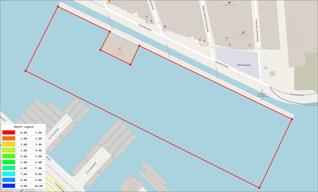
The first step is to down(load) a map and draw a boundary around the area to be surveyed.
Drawing a guidance line (optional)
When using the built-in auto placement tool, you have to set the direction of the cross sections. This will often be perpendicular to the dock or shore, or when performing a survey on a pond or lake, parallel to the direction of the wind, which makes it easier to sail straight lines. You can either set the direction of the lines by hand, by entering a heading in degrees, or you can use the direction of an existing cross section. We recommend to use the latter method.
In this example, we will draw a guidance line parallel to the jetty, so we can use it to generate parallel and perpendicular lines as well. We do this by manually placing a line. You can also use this method to place additional lines after you finished generating lines with auto placement. To draw a new section, right-click the map display and select the "Add Section..." option from the popup menu:
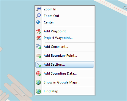
To create a new cross section by hand, right click the map and select "Add Section...".
After selecting the 'Add Section...' option, the 'Edit Cross Section' dialog box will appear. At this moment we do not alter settings, other than giving it a name, like 'Guidance,' since we are using this line as a guidance line for the cross sections we are going to generate. After clicking the "OK" button, a cross section will be placed at the cursor location. Now you can use the mouse to drag it to the correct position. Make sure that the 'Lock Objects' option is switched off; otherwise, it won't move from its place. You can find the "Lock Objects" option in the toolbar or the "Cursor" menu.
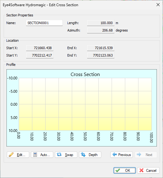
Just enter a name for the guidance cross section, and click "OK".
Use the center point of the section to drag it to another place, or the starting and ending points to resize and rotate it. For a demonstration, please check out the YouTube video in the first paragraph. In this example we will place the line parallel to the shore:

When using automatic placement, it is recommended to draw a "guidance line" first.
Generating perpendicular cross sections
When the boundary and guidance sections have been drawn, we can fire up the "Generate Cross Sections" tool. The easiest way to access this tool, it to right-click the "Sections" folder in the "Project Explorer" and selecting the "Generate Sections..." option. Alternatively, this option can be found under the "Tools" menu as well.
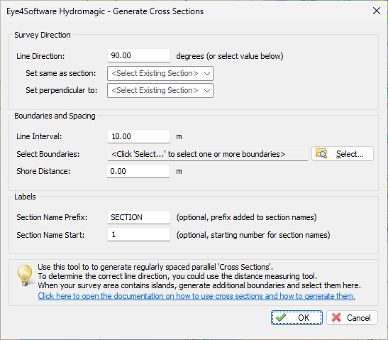
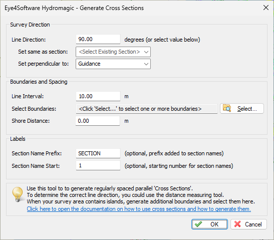
Use the "Generate Cross Sections" tool to generate cross sections perpendicular to the guidance line.
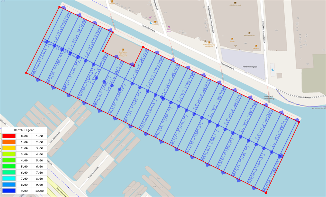
To generate lines perpendicular to the guidance line, select the name of the guidance line for the 'Set perpendicular setting. You will notice that the "Line Direction" has been set to the direction perpendicular to the guidance line. Also select the boundary for the survey area, as well as the boundaries for obstacles or islands (if any). Depending on the survey area, choose the spacing between the lines. This might be ten to twenty meters for large areas and as low as 5 meters when surveying near the shore or drop-off. The other settings will be discussed in the following paragraphs. When ready to generate the cross sections, click "OK" and the result should look like this:
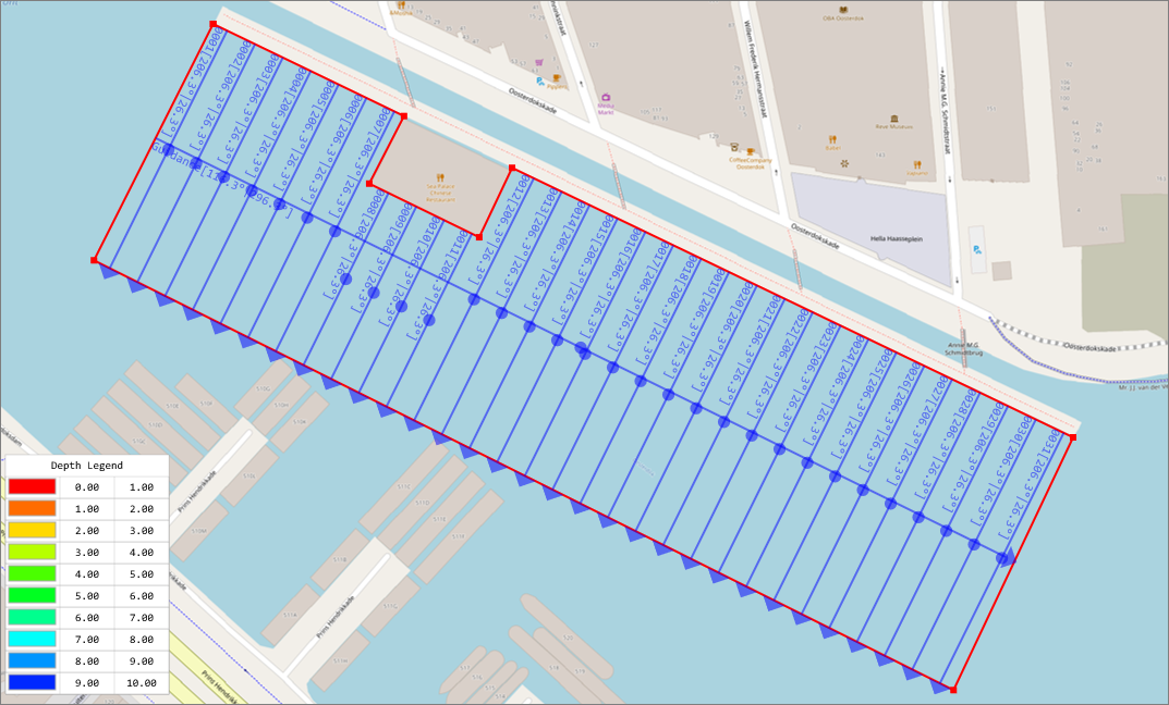
Example of cross sections generated perpendicular to the guidance line.
Generating parallel cross sections
Use the "Generate Cross Sections" tool to generate cross sections parallel to the guidance line.
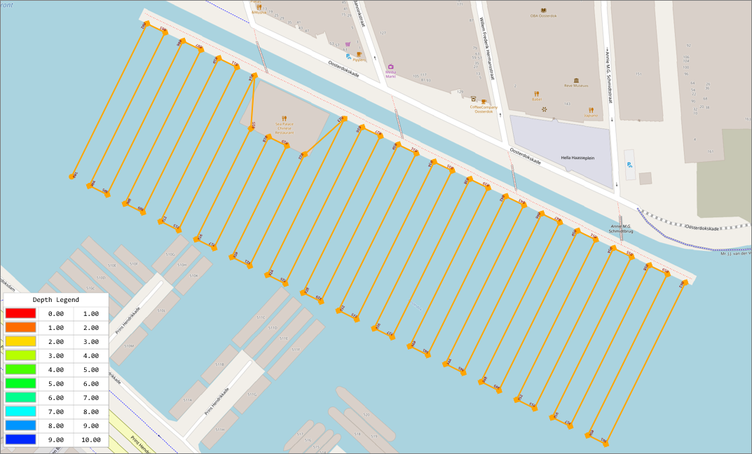
To generate cross sections parallel to the guidance line, Follow the same steps as in the previous paragraph. To get the lines parallel to the guidance line, select the name of the guidance line for the 'Set same as section' option.
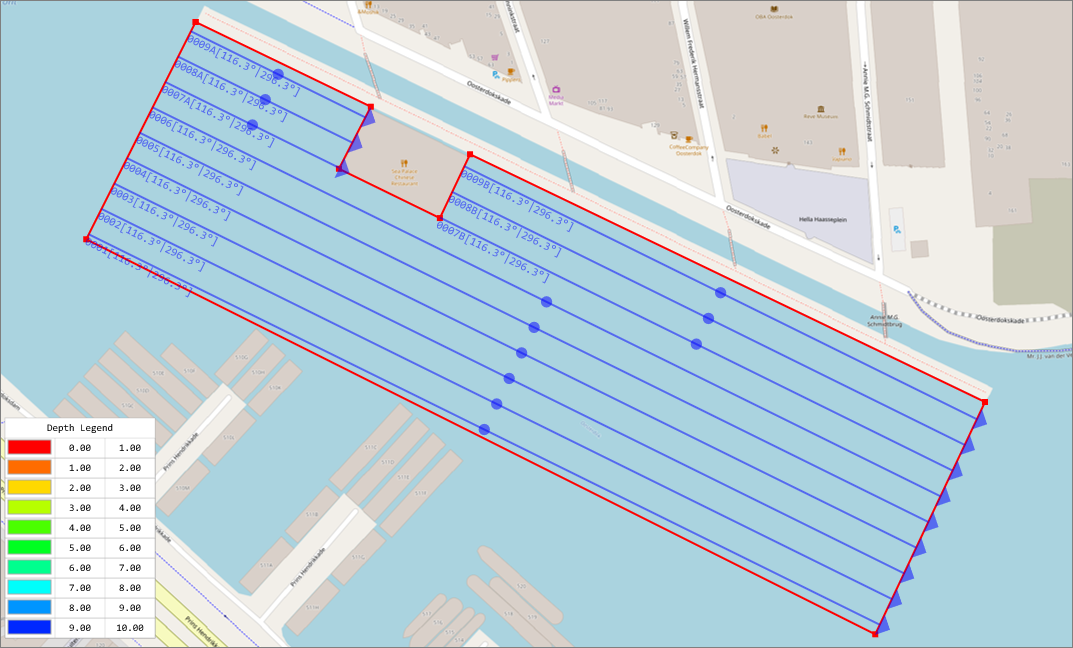
Example of cross sections generated parallel to the guidance line.
Cross Section Names
Typically, the name of a cross section consists of a number. To provide more clarity about a cross section, or to group them, the section number can be preceded by a short text. This setting is optional. To set a prefix for the cross section name, enter this value in the "Section Name Prefix" field. During cross section generation, Hydromagic will automatically check that there are no duplicate names generated. If this is the case, a notification will suggest another initial number, which can be selected in the 'Section Name Start' field, or you can accept the suggestion by clicking 'OK.
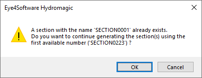
When there is a cross section name conflict, the software
will notify you and suggest an alternative name.
Alternating section directions
When looking at the examples above, you will notice that sections are drawn as arrows. This direction is useful to know when generating cross section images, so you know where the start and end of the cross section is on the map. It is also used to determine the direction when using an autopilot. In this latter scenario, the generated cross sections shouldn't be all in the same direction since you want to sail back and forth. This is where the "Use alternating section directions for route planning" is for. When you generating sections for use with the built-in route planner, make sure this option has been enabled, but make sure it is unchecked when generating cross sections that will be exported as images.
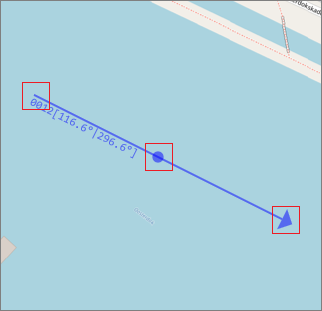
Use the "alternating section directions" option when using cross sections in the route planner...
...and your route is going to look like this.
Moving, resizing and rotating cross sections
After automatic or manual placement, you still might want to adjust the position of some of the cross sections. To do so, make sure the 'Lock Objects' option is switched off; otherwise, you won't be able to move anything. You can find the "Lock Objects" option in the tool bar or the "Cursor" menu.
You can move a cross section without altering its length or direction by hovering the mouse over the "dot" which is in the center of the section. As soon as the mouse cursor changes into a hand shape, you can click the right mouse button and move it to another place.
This works the same for the length or direction, but in this case you have to grab the arrow or start of the section with the mouse and move around. Now you will be able to rotate and change the length, but the cross section's center will remain on the same place.
When modifying cross sections like this, you can always press "Control"+"Z" on your keyboard to undo an action in case you made a mistake.
Grab a cross section with the mouse to rotate, move and resize.
Delete cross sections
There are two ways to delete a single cross section:
- Right-click the center anchor point of the cross section in the map, and select "Remove Section" from the pop up menu;
- Right-click the cross section name in the "Project Explorer" and select "Remove Section.
- Select the cross section in the "Cross Section Manager" and click the "Remove" button.
To delete all cross sections, right-click the 'Sections' folder in the 'Project Explorer' and select 'Remove All...' After confirmation, all cross sections will be removed from the project.
To delete multiple cross sections, you can use the Cross Section Manager, or select multiple cross sections in the "Project Explorer" when holding down the "Shift" key. When the selection is complete, just press the "Delete" key, or right-click the selection and select "Remove Sections..." from the popup menu.
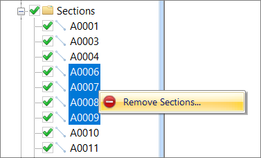
Hold the "shift" key to select multiple sections.
Cross Section Manager
The "Cross Section Manager" can be used to apply operations on more than one cross section at a time. The manager window lists all cross sections loaded in the project, and allows you to select multiple cross sections in order to toggle visibility, remove or reverse. The list of cross sections also shows you length and direction of each cross section.
Opening the Cross Section Manager
The "Cross Section Manager" can be opened from the "Project Explorer", normally situated on the left side of the main program window. If not visible, select 'Project Explorer' from the 'View' menu, locate the 'Sections' folder in the 'Project Explorer,' and right-click this folder. From the context menu which appears, select the "Manage Sections..." option as shown below:
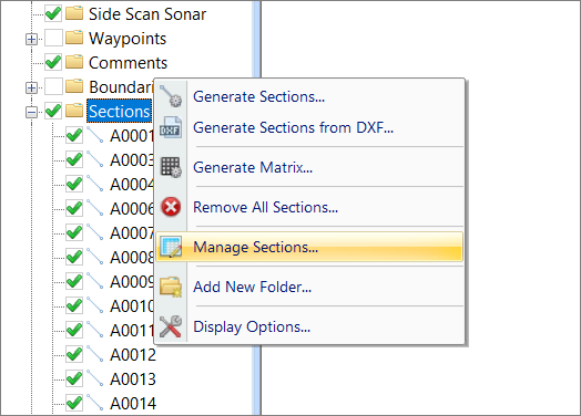
Right click the "Sections" folder and select "Manage Sections...".
Changing cross section order
From the "Cross Section Manager", you can alter the order in which the cross sections appear in your Hydromagic project. By changing this order, you will also change the order in which cross sections are selected when pressing the F11 or F12 keys, or the "Next Section" or "Previous Section" buttons in the main toolbar. When the order of the sections is different than the order in which you want to run your survey lines, just open the "Cross Section Manager" and right-click a cross section to change its position in the list by selecting one of the 'Move Up,' 'Move Down,' 'Move To Head,' or 'Move To Tail' options.
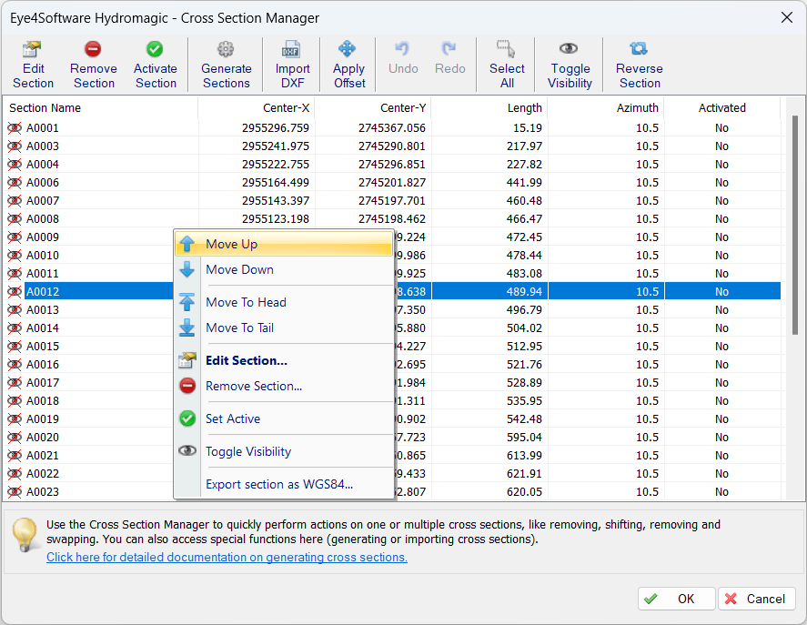
Right-click one of the sections to show the popup menu to change its position in the list.