
How to perform a PPK survey using Hydromagic
In cases where you need sub-centimeter accuracy, and you do not have direct access to a RTK base station, you can use PPK (Post Processing Kinematic) to (post)process your position data with base station observation data. This might be useful, for example when you are surveying at a remote area without cellular coverage to get your RTCM correction data in.
Since version 9.0, Hydromagic offers functionality to merge your survey data with PPK correction files to get a sub-centimeter accurate bathymetric survey. This functionality can be found under the miscellaneous tools window in the Sounding Generation Wizard. Before you can import this data, we will explain in the following paragraphs how PPK works and what steps needs to be taken to get to a PPK correction file which can be used in Hydromagic.
How does PPK work ?
When using RTK (Real Time Kinematic), the correction data is processes in real-time. This data can be received via an UHF radio link, Internet connection (NTRIP) or a cellular modem. As soon as your GNSS receiver starts applying this correction data to the calculated positions, it will report that the calculated position is "RTK-FIXED" and outputs the sub-centimeter accurate positions to your software as NMEA0183 sentences. Since the position data is already processed in real-time, there is no need to record any data on your GNSS receiver.
However, in cases where it is not possible to have an Internet or cellular connection (for instance when surveying in a remote area), you won't have access to this real-time correction data, thus not being able to send accurate position data to the acquisition software. This is where PPK can provide a solution. In this scenario we still record our inaccurate positions, but we use our GNSS receiver to obtain satellite observations like satellite ID, frequency (L1/L2/L5 etc), constellation, pseudo-range, carrier-phase, Doppler and signal-to-noise ratios. This information is stored into a RINEX or proprietary file format.
RINEX stands for 'Receiver Independent Exchange Format' and is widely used in PPK applications. Some receivers, like Trimble, may use their own proprietary data format (T01 Files) which can later be converted to RINEX files using a conversion utility. In general, most GNSS receivers capable of using RTK will also have the ability to record RINEX data. However, it is not possible to use a low cost GPS receiver to perform PPK, since they often lack the ability to store raw satellite data.
     2.11           OBSERVATION DATA    GPS(GPS)            RINEX VERSION / TYPE
cnvtToRINEX 3.13.0  convertToRINEX OPR  18-Mar-20 14:02 UTC PGM / RUN BY / DATE
----------------------------------------------------------- COMMENT
5037                                                        MARKER NAME
5037                                                        MARKER NUMBER
GNSS Observer       Trimble                                 OBSERVER / AGENCY
0000000000          TRIMBLE R8          2.32                REC # / TYPE / VERS
0000                TRM5800                                 ANT # / TYPE
  3865656.3134   408700.6538  5039818.1755                  APPROX POSITION XYZ
       -0.0649        0.0000        0.0000                  ANTENNA: DELTA H/E/N
     1     1     0                                          WAVELENGTH FACT L1/2
     5    C1    C2    L1    L2    P2                        # / TYPES OF OBSERV
  2020     3    18    13    40   17.0000000     GPS         TIME OF FIRST OBS
  2020     3    18    13    43   41.0000000     GPS         TIME OF LAST OBS
     0                                                      RCV CLOCK OFFS APPL
    18                                                      LEAP SECONDS
     7                                                      # OF SATELLITES
   G02   205     0   205    52    52                        PRN / # OF OBS
   G12   205   205   205   205     0                        PRN / # OF OBS
   G14   205     0   205   205   205                        PRN / # OF OBS
   G25   205   205   205   205     0                        PRN / # OF OBS
   G29   109   109    99   109     0                        PRN / # OF OBS
   G31   205   205   205   205     0                        PRN / # OF OBS
   G32   205   205   205   205     0                        PRN / # OF OBS
CARRIER PHASE MEASUREMENTS: PHASE SHIFTS REMOVED            COMMENT
                                                            END OF HEADER
 20  3 18 13 40 17.0000000  0  7G02G12G14G25G29G31G32
  22896097.25014                   -646440.76614    -61686.77355  22896098.34455
  20629016.32813  20629012.90258    -20116.17213   -494386.87158
  22369093.21116                  -2749656.47716  -2119735.49656  22369090.06356
  19943364.90616  19943364.63359  -3483047.49616  -2645851.85559
  21958858.10211  21958858.57058   -625176.19511  -2234498.48058
  23272064.16414  23272065.71157  -3630352.94114  -2333282.91857
  22236046.75015  22236044.76658  -1067563.27715   -823457.18458
Short fragment of a RINEX file recorded on a GNSS receiver (Trimble R8)
Starting a PPK survey
The actions involved to start a PPK survey on your GNSS receiver will be different for each vendor and model, some have a button to start recording, while others need a field computer or survey controller to start recording data. It is imported to start the PPK survey on your receiver BEFORE recording raw data in Hydromagic, end you have to end the survey on your receiver AFTER you stopped recording in Hydromagic. Please note that some receivers need some time to initialize and wait to have enough satellites in view. For Trimble this takes about 8 minutes, so start your receiver well in advance.
Before starting the survey, please check the configuration of your GNSS receiver. You might want to check whether recording is enabled and that the recording interval is set to at least one observation per second. An example of how to set up and start your receiver can be found here: How to start recording PPK survey data with a Trimble TSC2 controller .
Collecting RINEX files from your receiver
Again, this may require a different approach for each brand of GNSS receiver. Some might have the ability to store the RINEX data on a SD card, so you can easily transfer the files to the PC, while others need special software to import it from the receiver and convert it to RINEX format. The most important is that you end up with a file that looks like the example above.
Converting Trimble T01 files to RINEX files
When using a Trimble receiver (you can skip this paragraph when using any other brand), all satellite and navigation observations will be stored as T01 files on either the receiver or the controller (depending on the survey style settings). After transferring the T01 file(s) to your computer, go to a search engine and look for the "ConvertToRINEX" utility and it should appear in the search results.
Use the installer to install the software and execute it using the Windows Start Menu. Then go to "File" => "Open..." and select the T01 files you want to convert. After selecting one or more files the utility should show something like this:
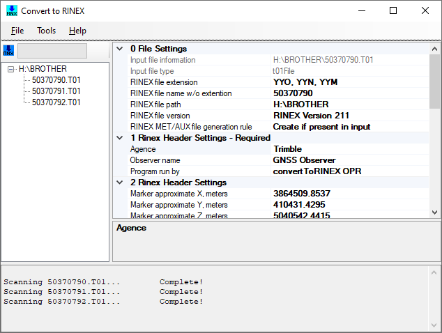
Convert Trimble T01 files to RINEX files using the Trimble ConvertToRINEX utility
When the input files have loaded without errors you can proceed to the next step, which is converting the loaded data into actual RINEX files. To do so, select the "Convert Files" option from the "File" menu as shown in the screenshot below:
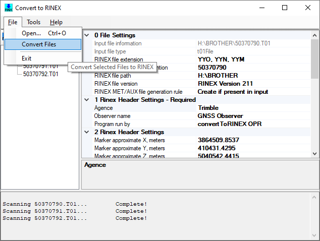
Select the "Convert Files" option from the "File" menu to create the RINEX files.
The software will now convert the data to RINEX format. The resulting files will be written in the same folder as where the input files reside. After this last step you can close the utility. The resulting files will have the ".20n" and ".20o" extensions, where the ".20n" file contains the navigation data and the ".20o" file contains the satellite observation data. Both files are required to generate the final correction file(s) for Hydromagic.
When there is correction data for GLONASS as well, there will also be a ".20g" file. Please note that the "20" in the file extension indicates the year the data was recorded. This means that it is possible to encounter ".18o", ".19o" files as well.
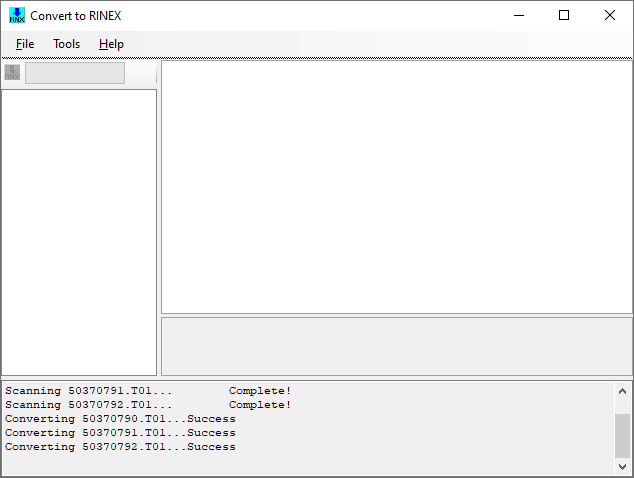
The utility has successfully written the RINEX files.
Obtaining correction network files
To correct the collected data, you need a second set of RINEX data files from a reference network such as CORS, EUREF, IGS or (commercial)local networks. How to obtain these files may differ per country or area, in this example we will show this process for the CORS network in the United States. The user-friendly CORS website can be visited at https://www.ngs.noaa.gov/UFCORS/.
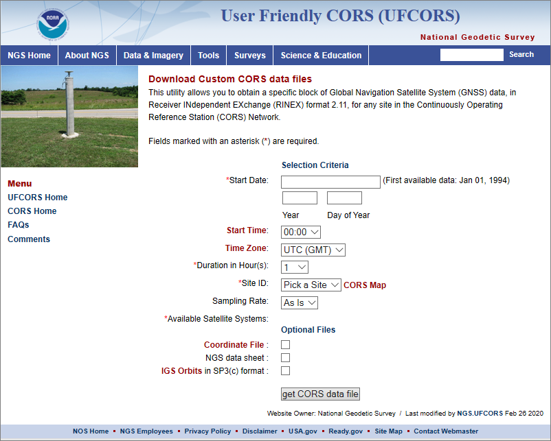
Use the CORS website to get RINEX correction data for the U.S.
Selecting CORS data - time span
Start Date
Select the date of your survey here. You can open a calendar control by clicking the first entry box. After selecting a date, the "day of year" will also be displayed. You will find this day of year in the file names of the generated files as well (along with the site id).
Start Time
Select a start time which is at least a couple of minutes in advance of the start of your survey. You can find the start time of your survey by analyzing your raw data. Please note that the data displayed in this tool is in local time.
Time Zone
Select the appropriate time zone for your survey data. When you have entered the start time as UTC, GMT or GPS time, leave this setting as is: "UTC(GMT)".
Duration in hours
Select enough hours to cover your whole survey. Take into account that the start time of your survey has been rounded down since you can only select whole hours.
Selecting CORS data - site
To get the best results, pick the site which is the nearest to your survey location. However, keep in mind that not all sites keep track of all satellite systems. To check this, click the "CORS map" URL to have a look at the capabilities of the CORS sites near you. When you are using for instance a GNSS receiver which tracks GLONASS as well, you might want to select a site which tracks these satellites as well. There are also differences in the amount of data that is recorded (interval). This legend helps you select the best site near you:
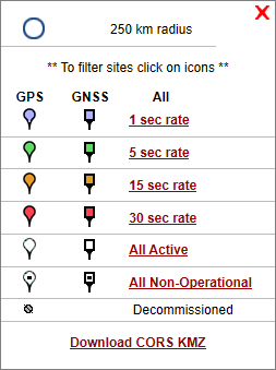
Legend which shows the capabilities for CORS sites
After selecting a site, choose which GNSS frequencies and constellations you wish to use. These should match the capabilities of your GNSS receiver:
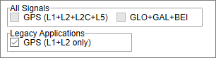
Select which frequencies and constellations your GNSS receiver supports
Selecting CORS data - options
After selecting time span and CORS site, check the three boxes at the bottom of the form. The first two files are not required, but are nice to have, while the SP3 file adds additional accuracy.
Next click the "get CORS data file" button to download a ZIP file containing the correction files needed for the RTKLib (or other) software. The downloaded file will contain a couple files which should be extracted from the archive. The files with the extensions ".20n", ".20o", ".20g" (GLONASS only) and ".sp3" are required. Some other network's may provide only a ".20n" and ".20o", but for CORS we will be using the ".sp3" file as well.
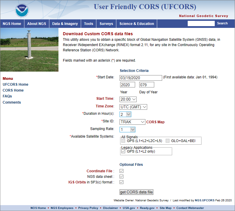
Example settings for a survey perform at March 19th 2020.
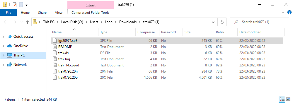
Example of the files contained in a CORS ZIP archive.
Downloading and installing RTKLib
Now we have collected RINEX observation and navigation files for both the base and rover, we can combine this data to get a file with the corrected position and elevation information. For this, the RTKLib open source package can be used, which binaries can be downloaded free of charge from GitHub: https://github.com/tomojitakasu/RTKLIB_bin.
On the GitHub page, just click the "Clone or Download" button, and click "Download ZIP". When downloading has completed, you can extract the files to a folder on your hard-drive. Browse to the folder where the files have been extracted and start the "rtkpost.exe" application:
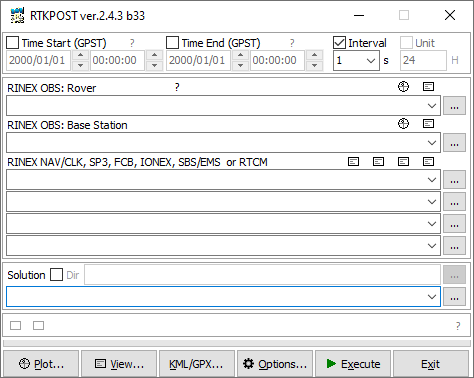
The main screen of RTKLib's RTKPOST application.
Setting up the RTKPOST utility
Before selecting the input files, let's got through the different configuration windows RTKPOST has to offer, to make sure we end up with a useful PPK correction file. There are a total of seven configuration tabs in the RTKPOST utility which can be accessed by clicking the "Options..." button:
- Setting 1;
- Setting 2;
- Output;
- Statistics;
- Positions;
- Files;
- Misc.
For some you can use the default settings. Others need some modifications in order to get the correct data for use in Hydromagic. The following paragraphs discuss in detail what the (most of the) different settings do, and which ones we need to adjust.
RTKPOST Configuration - Setting 1
Since we want to do post processed kinematic, set the first setting, the "Positioning Mode" to "Kinematic". There is also a mode called "PPP Kinematic", but this mode does not apply to cases where a base station and rover setup is involved.
The "Frequencies" setting can be used to process only the frequencies which are received by your receiver. In most cases "L1+L2" will work. When your receiver is capable of receiving the "L5" frequency band as well, set this option to "L1+L2+L5". Set the filter type to "Combined" to combine the "Forward" and "Backward" filter options for smoother data.
In GNSS receivers, the elevation mask is used to ignore satellites which are low on the horizon. This is because atmospheric and multi-path errors are the worse for those satellites. Set the "Elevation Mask" setting to the same setting as used by your receiver, which is usually 10 degrees. If you are unsure, leave the default value.
Set "Rec Dynamics" as well as the "Earth Tides Correction" settings to "OFF". We found that switching on the "Rec Dynamics" function was sometimes resulting in an empty correction file (which has something to do with the receiver used, or the fact that in our test the receiver wasn't moving). You can try to switch this feature to "ON" later, after a first successful attempt with the feature switched to "OFF".
At the bottom of the screen, check the boxes for the satellite constellations your receiver supports (GPS, GLONASS, Galileo, QZSS, SBAS, Beidou or IRNSS. Depending on the receiver used, your settings should now look like this (Example shows a GPS only GNSS receiver capable of receiving the L1 and L2 GNSS frequencies):
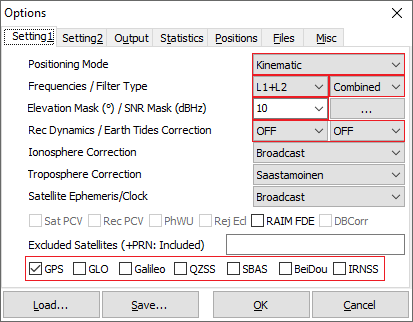
The first settings tab of RTKLib's RTKPOST application (Setting 1).
RTKPOST Configuration - Setting 2
In this setting, only check the "Integer Ambiguity Res" setting. It should be set to "FIX and Hold". The settings in the screenshot below should work fine for most cases (these are the defaults):
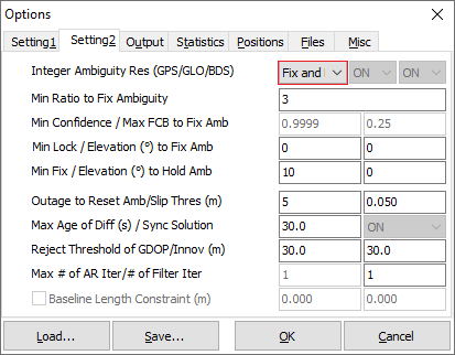
The second settings tab of RTKLib's RTKPOST application (Setting 2).
RTKPOST Configuration - Output
The output settings are used to define the way output data is written and formatted. It is important to use the correct settings in order to be able to use the resulting file in Hydromagic (with the default Hydromagic settings).
The format of the corrected rover positions should be written as WGS84 geographic coordinates, so we have to set the "Solution Format" setting to "Lat/Lon/Height". This results in the XYZ positions being written in the file like this: "52.553813441 6.062388710 43.5980".
Although not required, it is recommended to set the "Output Header" and "Output Processing Options" to "ON". With these options switched on, there will be some additional information written at the start of the file. Since these comments are ignored by Hydromagic, it is a nice to have this additional information case of troubleshooting.
To match the position records with the existing data in your Hydromagic project, it is important to have a good time stamp. Select "hh:mm:ss UTC" for the "Time Format" setting since Hydromagic uses UTC time stamps to merge the data. When you generate more then one record per second, also make sure the "# of Decimals" is set to "3".
As for the height settings, set the "Datum" to "WGS84" and "Height" to "Ellipsoidal". We just want the WGS-84 Ellipsoidal height in the correction file since we will (optionally) convert to a local vertical datum in Hydromagic.
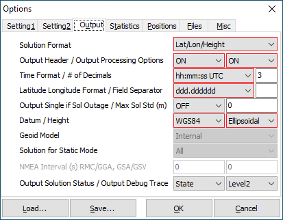
The output settings tab of RTKLib's RTKPOST application (Output).
RTKPOST Configuration - Positions
In this tab we need to set the position of the base station we are using. This can be auto-detected from the RINEX file obtained from the base station. When the RINEX file contains this data, there should be an XYZ position (in ECEF coordinates) in the header of the file:
3859986.8933 424911.6802 5042814.6612 APPROX POSITION XYZ
In this case, set the base station position to the "RINEX Header Position" setting. In the unlikely event that this information is missing, select the "Lat/Lon/Height" option and enter this info manually. After checking the configuration in the "Positions" tab, click "OK" to store the settings and start processing the data.
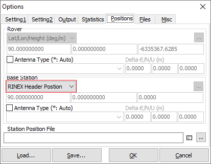
The positions settings tab of RTKLib's RTKPOST application (positions).
RTKPOST Processing
When configuration of the software has been completed, we can finally start generating the correction file. To do so, we have to specify both the base station and rover RINEX files. When we also own a SP3 file (for example when using CORS), we need to set the location of this file as well. Always make sure that the rover and base files overlap in time, otherwise you will end up with an empty correction file.
The example below shows how to load the files. Just click the browse button (marked in blue) for the "RINEX OBS: Rover" and "RINEX OBS: Base Station" fields (marked in red). Any additional files (such as a SP3 file) can be selected into the four additional fields (marked in orange) below the base station file. Please note that there is no need to specify more then one RINEX file of the same set. For instance, when you have a ".20o", ".20n" and ".20g" files, just select one of the files and the other(s) will be loaded automatically as needed.
The location of the resulting correction file is set automatically in the output field (marked in green). You can alter this location by clicking the browse button right to this field. When a file already exists, you will be prompted whether it should be overwritten when you start the processing.
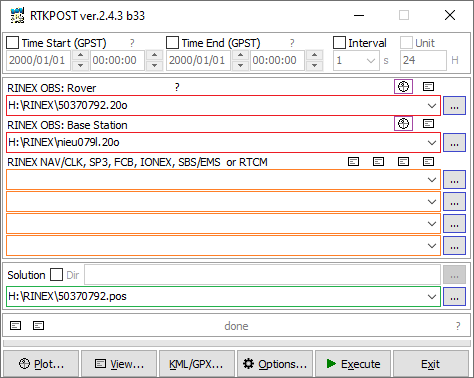
Select the RINEX files to use for the computation of the correction file.
RTKPLOT Utility (optional)
To check the validity and time coverage of the input rover and base station RINEX files, you can load them in the "RTKPLOT" utility by clicking one of the "plot" buttons associated with the input files (marked in purple). Do not use the "Plot..." button at the bottom of the screen. This one can be used to plot the final result.
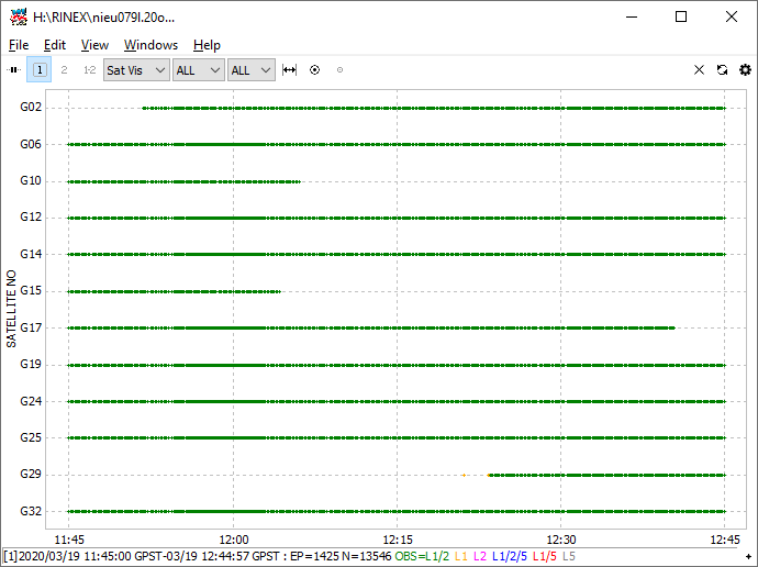
The plot for the RINEX observation file shows the time span and the satellite visibility.
Generating the correction file
After specifying the input and output file(s), and after checking the input RINEX observation files with RTKPLOT (optional), click the "Execute" button to start generating the correction file. The progress is shown during the creation of the correction file, and the "Q" value in the progress bar already shows the quality that is obtained, which should be "1":
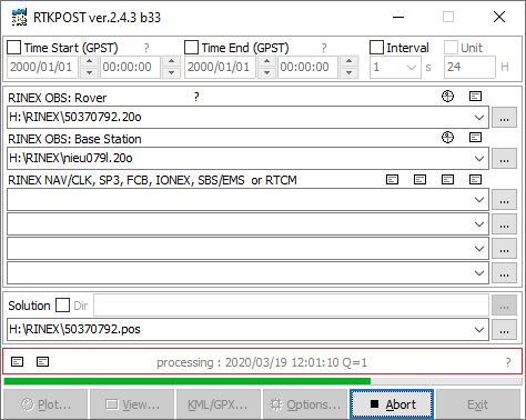
The obtained quality will be shown above the progress indicator during data-processing.
When the progress indicator shows "done" the correction file has been written successfully. You can click the "View..." button to show the result as ASCII text, or click the "Plot..." button to show the result on a map. The resulting correction file should look like the one below. Please make sure that the base station coordinates are set, and the quality fields (Q) have the value of "1", which means kinematic fix:
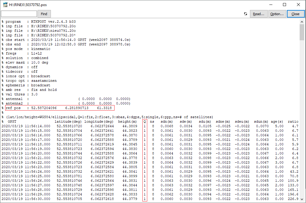
The resulting PPK correction file generated with RTKPOST.
When the file looks like the example above, and contains corrected coordinates for your complete survey, you can continue applying the PPK correction files to the raw data files collected in Hydromagic.