
Channel Design
In Hydromagic, a channel design is used for volume calculations using cross-sections or to generate a reference matrix for dredge monitoring. A channel design is generated by modifying the depth or elevation profiles of generated cross-sections. Cross-section profiles are stored as pairs of distance and level data, where the distance is the distance measured from the start of the section (indicated by the label in the map view, while the end of the section is drawn as an arrow).
When the depth and the slope of the shore are known, it is possible to calculate depths or elevations on the cross-sections automatically. Before creating a channel design, you must first draw a boundary of the area and generate sections for this area.
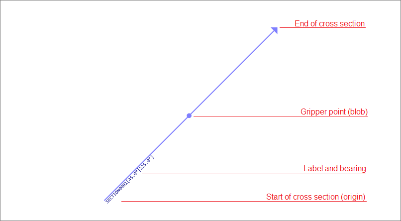
A cross section starts at the label and ends with an arrow. The profile distance or offset is measured from the start.
Calculating depth or elevation profiles
To alter a cross section's profile, just right-click on the gripper point in the map display and select the 'Edit Section...' option from the pop-up menu.
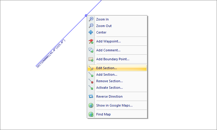
Right-click on the gripper point in the map display, and select "Edit Section..." option.
When first editing a cross section, you will notice the profile display is empty, this is because no depths are stored by default. In this example, we will create a channel with a maximum depth of 5 meters and a slope of 50 percent.
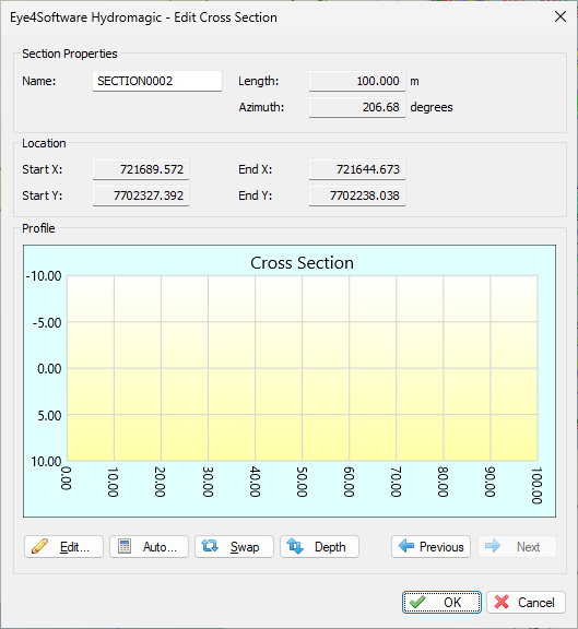
Right-click the section and select 'Edit Section...' to modify the cross section.
This means that for each 2 meters, the bottom depth increases by 1 meter. When the bottom depth increases by 1 meter for each 4-meter extra distance from the shore, the slope is 25%. To calculate profiles from this setting, click the "Auto..." button. The following dialog should now appear:
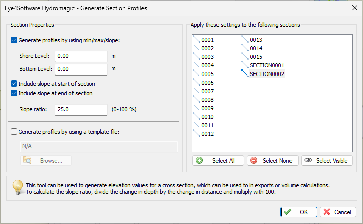
Using the "Generate Section Profiles" dialog, you can generate a profile for one or more sections.
In the left section of the dialog, you can enter the channel design parameters, in the right section, you can select the cross sections you want to apply these parameters to. In this example, the depth at the shoreline should be half a meter, at the waterway axis, the depth should be 5 meters. The slope used is 50 percent. Click the 'OK' button to apply these settings. The graph display will now look like this:
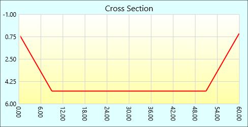
An automatically generated profile using a slope on both sides of the channel.
Check the other sections by browsing through them using the next and previous buttons.
Manual editing
In cases where calculation is not usable, for instance, when a different slope is used on either side, or when a section is not placed between shores, you must enter the distance and depth values manually. To do so, click the 'Edit...' button to open the profile editor:
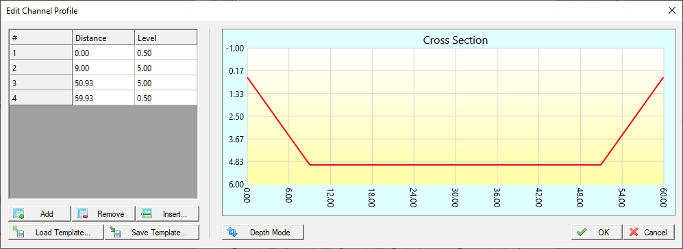
A depth or elevation profile can also be edited manually by entering values.
The table on the left of the dialog allows you to alter, insert, and delete distance-depth pairs.
Changes made are directly visible in the graphical display. When done, click 'OK' to store your design.
Checking the profiles
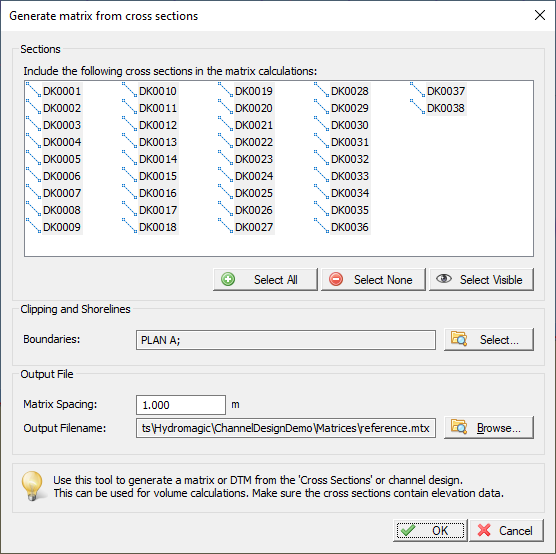
The quickest way of checking whether all profiles have been created correctly, is by creating a matrix using cross-sections. To do so, select the "Generate Matrix..." option from the "Sections" folder in the "Project Explorer".
Right-click the 'Generate Matrix...' option to build a matrix from cross-section profiles.
Select the correct boundary (in most cases, the boundary used for auto placement of the sections), a file name for the matrix, and the spacing used (can be larger for a test, for volume calculation, use the same spacing as the matrix created from the sounding. Click "OK" and check the result.
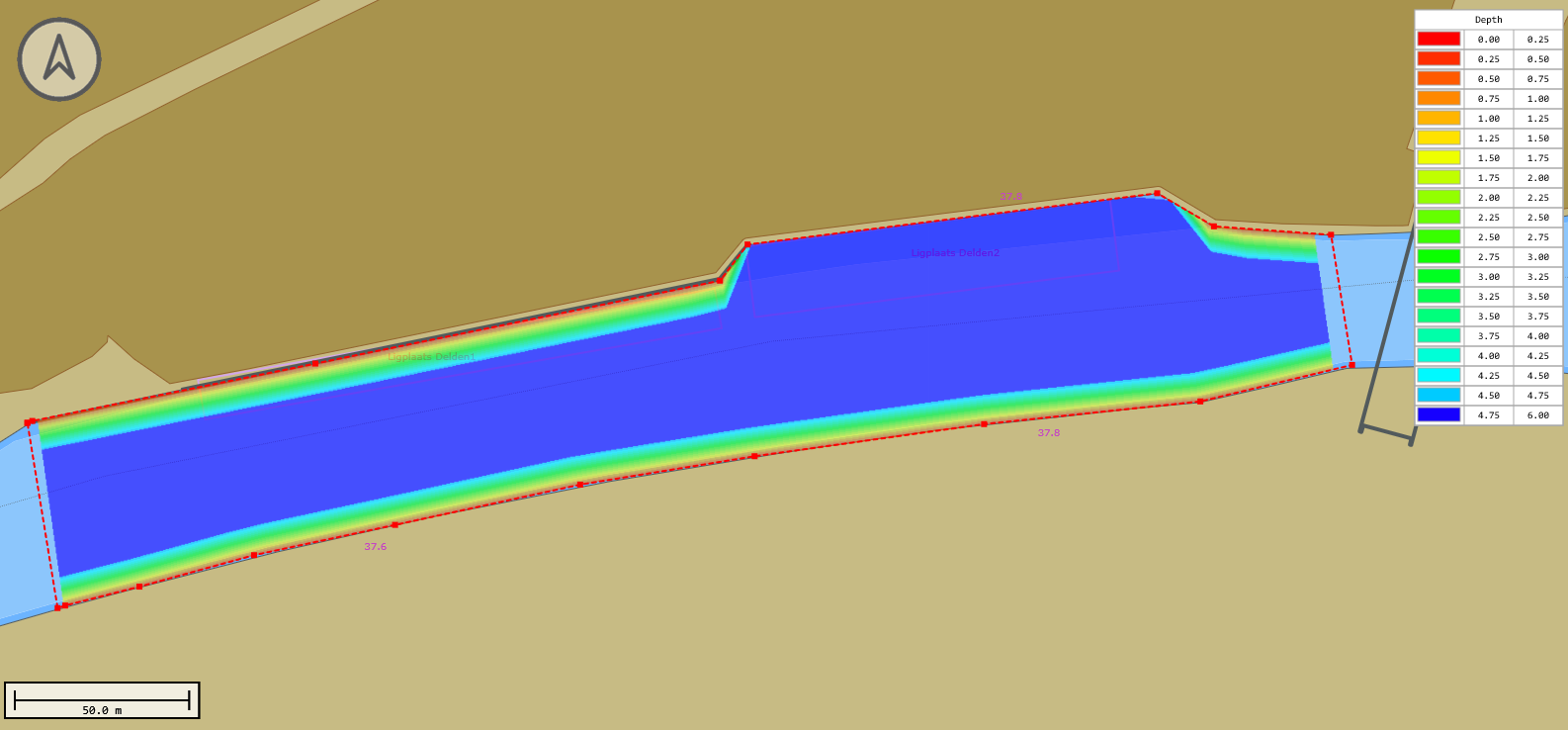
Reference matrix generated from a channel design - Please do not forget to select a color scheme to visualize the matrix.
Video Tutorial
The following YouTube video tutorial demonstrates how to generate a matrix from a channel design in Hydromagic. Click below to play the video. When you like the video, please click the like button and subscribe so you will receive an update when new video tutorials on Hydromagic are uploaded.
Use cross sections to generate a design matrix.